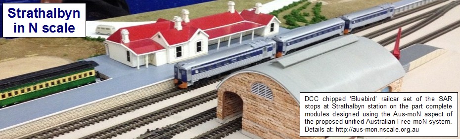
This blog is a summary of the progress of the building of an N scale layout representing Strathalbyn station and yards in South Australia. The era being modelled is the 1960s. The Aus-moN free form modular system was chosen as the basis for construction. Besides operational use, the layout is also suitable for display. As Strathalbyn station is still in use today by tourist trains of SteamRanger, a swap era may be considered to add variety. (by the Southern N Scale Modellers informal group)
Thursday, 27 December 2012
Wiring Completed for Middle Section Module
Wiring has been completed and tested for the middle section module. A picture may be viewed under Wiring in the menu. Wiring will commence soon on the two outer section modules.
Thursday, 15 November 2012
Commencement of Wiring
With the completion of the multi-track butt-joins between the three sections, wiring is to begin. An initial wiring schematic and sample connectors can be viewed at the Wiring page.
Wiring has begun on the middle section module. Wiring is a slow process. A picture of the middle section wiring will be uploaded when it is completed.
Wiring will be completed and track operation tested before any track is permanently tied in position. Full operational running will be carried out before any ballasting is considered.
Saturday, 20 October 2012
Track Placement Completion
All the yard trackage has now been tacked in place with track pins. The 'bake
& cooking paper' was ripped away, except for the pieces showing the
location of the station and the goods shed. The next stage will be the making of the butt-joins at the two interfaces of the sections. The ends of the outer modules are still to have the end-plates fitted.

Friday, 19 October 2012
Turntable and Initial Track Placements
The 57ft turntable (originally a 73ft Peco turntable before being 'reduced in diameter') was test fitted into the baseboard.


Following the test fitting of the turntable, the central section track plan was drawn on two strips
of 'bake & cooking paper' taped together and then taped to the top of the baseboard. It would be ripped away
once all track is down.
The initial trackage was laid in the loco facilities area and one end of the station. As each electrofrog turnout was positioned, a hole was drilled for a turnout control rod (if or when used). Initially, turnouts will be operated directly by hand. The stock rails and frog rails opposite the turnout blades end will have insulated joiners fitted. An electrically conductive grease may be used to improve conductivity between the turnout blades and stock rails.
The initial trackage was laid in the loco facilities area and one end of the station. As each electrofrog turnout was positioned, a hole was drilled for a turnout control rod (if or when used). Initially, turnouts will be operated directly by hand. The stock rails and frog rails opposite the turnout blades end will have insulated joiners fitted. An electrically conductive grease may be used to improve conductivity between the turnout blades and stock rails.

A
sample goods shed was used for a test placement. The actual
Strahalbyn goods shed has the platform at the opposite end of the
building. More on the goods shed and other structures later.

Thursday, 18 October 2012
Wednesday, 17 October 2012
Introduction and Plan
Strathalbyn railway station is a former station on the South Australian Railways broad gauge line from Adelaide to Victor Harbor. The station is still currently in use, both as a
railway station and as a Visitor Information Centre. SteamRanger
Heritage Railway currently operates tourist trains through Strathalbyn;
the SteamRanger website has a short history of Strathalbyn station.
Fortunately, as the station and yards can fit into a 4m x 0.7m area in N scale using virtually no compression, a portable layout was considered to be reasonably easy to make using a standard modular system as the basis for the modules. As not all of the module sections would be rectangular in shape and as DCC (Digital Command Control) would be used to control the trains, the Aus-moN free form modular system, still under development, was chosen as the basis for construction. The layout would consist of three sectional modules. A central module of approximately 1800mm x 600mm and two end modules of approximately 900mm long each with one end incoporating a 20 degree curve diminishing the width to 400mm. Layout height to top of rail would be a nominal 1200mm. Peco Code 55 track and turnouts were chosen to be used as the Peco track represents the prototype track more closely. The free download version of XTrackCAD was used to design the layout plan.
Modules representing the river bridges and the flour mill and adjacent wheat silo (with siding) may be considered at a later stage, as may also Sandergrove junction station.
Modules representing the river bridges and the flour mill and adjacent wheat silo (with siding) may be considered at a later stage, as may also Sandergrove junction station.
I wish to acknowledge fellow modellers who are involved with this project; Greg, Mark, Stuart, Rodney and Peter.
 |
| (Strathalbyn Station - Mid 1960s) |
XTrackCAD diagram of the modular layout plan:


Subscribe to:
Posts (Atom)