Rail. All track and turnouts are Peco Code 55.
Turnouts. The stock rails and frog rails opposite the electrofrog turnout blades end have insulated joiners fitted. An electrically conductive oil/grease may be used to improve conductivity between the turnout blades and stock rails. Electrifying blades with an additional switching mechanism to ensure reliability will probably be installed later.
Turnouts. The stock rails and frog rails opposite the electrofrog turnout blades end have insulated joiners fitted. An electrically conductive oil/grease may be used to improve conductivity between the turnout blades and stock rails. Electrifying blades with an additional switching mechanism to ensure reliability will probably be installed later.
Wiring will be completed and track operation tested
before any track is permanently tied in position. Full operational
running will be carried out before any ballasting is considered.
Butt-Joins between sections. A razor saw was used to cut through the rails above the fine join gap once the rails had been soldered in position on the printed circuit board strips. As the strips are located in position by screws, fine adjustments, if necessary, may be made by loosening the screws and then retightening after position adjustment. If stability appears lasting, then the strips may be glued down.
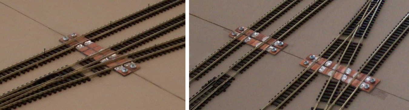
Module Interface Butt-Join. Each rail was soldered to the top of a brass screw located near the centre of the 18mm thick plywood End Plate. The second sleeper in was first removed. A dropper wire was soldered to the metal joiner connecting the butt-join rail to the rail of the turnout.
 Clamp-on Head Shunt:


.jpg)


Fiddle Yard ('Adelaide'):
Ballasting. Station area trackage ballasted. Fine grade 'Mountain Ash' purchased from Junction Models hobby shop was used.
No comments:
Post a Comment